Build and Test of Open Source 3D-Printed 1000 μL Micropump
Overview and Scope:
In the publication, Open source 3D-printed 1000 μL micropump, Dr. Jorge Bravo-Martinez provides a concise and convenient method to create a 3D printed pipette, termed ‘micropump’, which fulfills many of the tasks of industry standard pipettes at a fraction of the cost. The author of this publication cites the expensive costs associated with research, especially for common laboratory equipment, tools, and consumables. Therefore, the author proposes this micropump as a cheap and effective alternative to commercial pipettes to lower the costs associated with scientific research through the use of open source technology.¹ This handy gadget is a testament to the author’s mention of the “open-source revolution”. Specifically, the author cites examples of how many state of the art laboratories are able to cut their operating costs significantly by implementing open source 3D printing technology. This also creates huge potential for laboratories and researchers in emerging markets, which cannot always afford the newest technology. The implementation of open source technology is groundbreaking, as it allows for the top researchers to cut laboratory operating costs significantly and also allows researchers who have a tight budget to access the necessary tools and equipment to further research. This ultimately leads to an overall increase in efficiency of research institutions and research productivity worldwide.
In this post, we build and test the feasibility of this micropump using open source technology. We found that this micropump was a utilitarian piece of equipment that was relatively easy to reproduce, required minimal knowledge, and required almost no deviation from the original build instructions provided in the publication. This micropump is essentially an amalgamation of a graduated pipette and a micropipette. Although the micropump operates slightly different than standard microbiology pipettes, it is very neat and handy nonetheless. It can be reasonably constructed within a 24 hour period and is inexpensive to produce. The author states that this micropump can be used effectively for common laboratory procedures, but may not be effective for conducting very precise laboratory procedures, such as PCR.
Parts List:
Ender 3 V2 3D Printer
PLA (or any other filament of choice) - Used eSUN PLA PRO (PLA+) 3D Printer Filament, Dimensional Accuracy +/- 0.03mm, 1kg Spool, 1.75mm, Blue - https://www.amazon.com/dp/B01EKEMNRO/ref=twister_B095MTT7D3?_encoding=UTF8&psc=1
General tools: hex keys, screwdrivers, sandpaper, etc.
STL files - (https://www.thingiverse.com/thing:2677215) or files found in https://doi.org/10.1016/j.ohx.2017.08.002 - https://data.mendeley.com/datasets/jj65p3znnr/1 - https://3dprint.nih.gov/discover/3dpx-007460
2x - 2.5 x 20mm Phillips flat head screws
1x - 10-24 x 1” course socket screw (recommended to use a 5M x 25mm headless socket screw in publication)
1x - 1mL Norm-Ject luer lock syringe - https://www.amazon.com/Plastic-Syringe-Luer-Slip-Norm-Ject/dp/B01HDYBGNA
Epoxy or waterproof silicone adhesive - Used J-B Weld ClearWeld - https://www.amazon.com/J-B-Weld-50112-Clear-0-85/dp/B009EU5ZM0
Printer Settings:
Sliced using Ultimaker Cura 4.10.0
Filament: eSUN PLA PRO (PLA+) 3D Printer Filament, Dimensional Accuracy +/- 0.03mm, 1kg Spool, 1.75mm, Blue
Standard Quality - Resolution: 0.20mm
Infill: 50% for all components, 90% infill for nozzle
Supports: tree, 45% overhang, zigzag pattern
Extruder Temperature: 215°C
Bed Temperature: 60°C
NOTE: See publication for original printing parameters
Components and STL Files:
There are five components which need to be 3D printed for this micropump:
The files used for the print in this post were found and retrieved from an upload by JorBraMar on Thingiverse.²
Below is a list of the original file archive links.
Body - doi: http://dx.doi.org/10.17632/jj65p3znnr.1 - https://3dprint.nih.gov/discover/3dpx-007460
Cap - doi: http://dx.doi.org/10.17632/jj65p3znnr.1 - https://3dprint.nih.gov/discover/3dpx-007460
Gear - doi: http://dx.doi.org/10.17632/jj65p3znnr.1 - https://3dprint.nih.gov/discover/3dpx-007460
Nozzle - doi: http://dx.doi.org/10.17632/jj65p3znnr.1 - https://3dprint.nih.gov/discover/3dpx-007460
Slide - doi: http://dx.doi.org/10.17632/jj65p3znnr.1 - https://3dprint.nih.gov/discover/3dpx-007460
Note: Nozzle is printed with 90% infill, all other components are printed with 50% infill.
Assembly:
Carefully remove any support material or excess filament. Begin by sanding the inside of the Body to ensure it is smooth and will allow the Slide to move seamlessly.
Ensure all of the components fit together properly and that there are no defects in any of the components.
Place the 1mL syringe in the Nozzle and make sure that the Nozzle is clean and not obstructed. If the syringe fits well, then prepare an epoxy glue or waterproof silicone sealant. Place the glue on the outside of the syringe and carefully begin placing the syringe into the Nozzle, ensuring there is sufficient sealant to maintain an airtight seal. Remove any excess adhesive that may obstruct any of the components of the syringe. Let the adhesive dry for the recommended time and ensure the final product is sealed strongly.
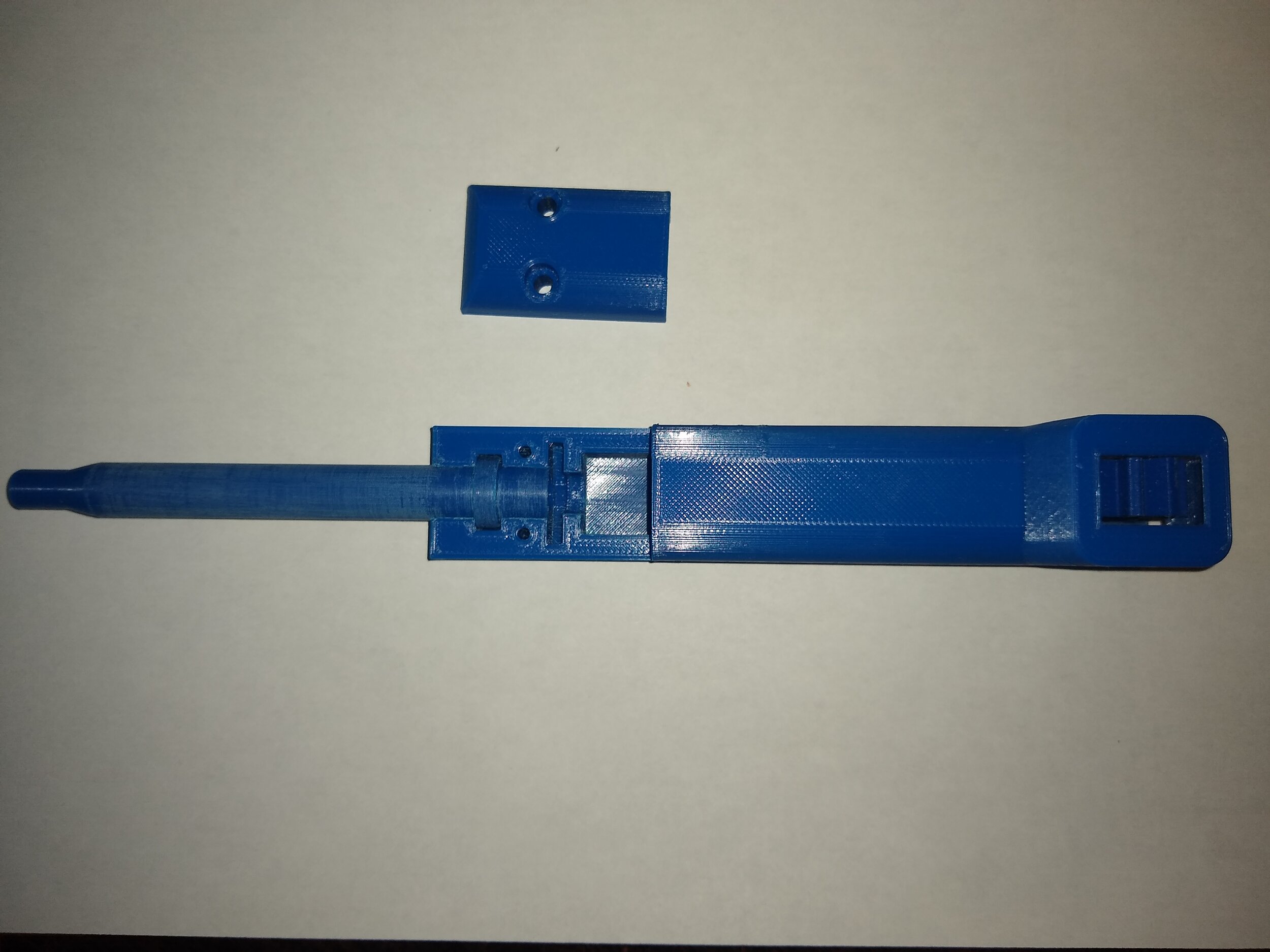
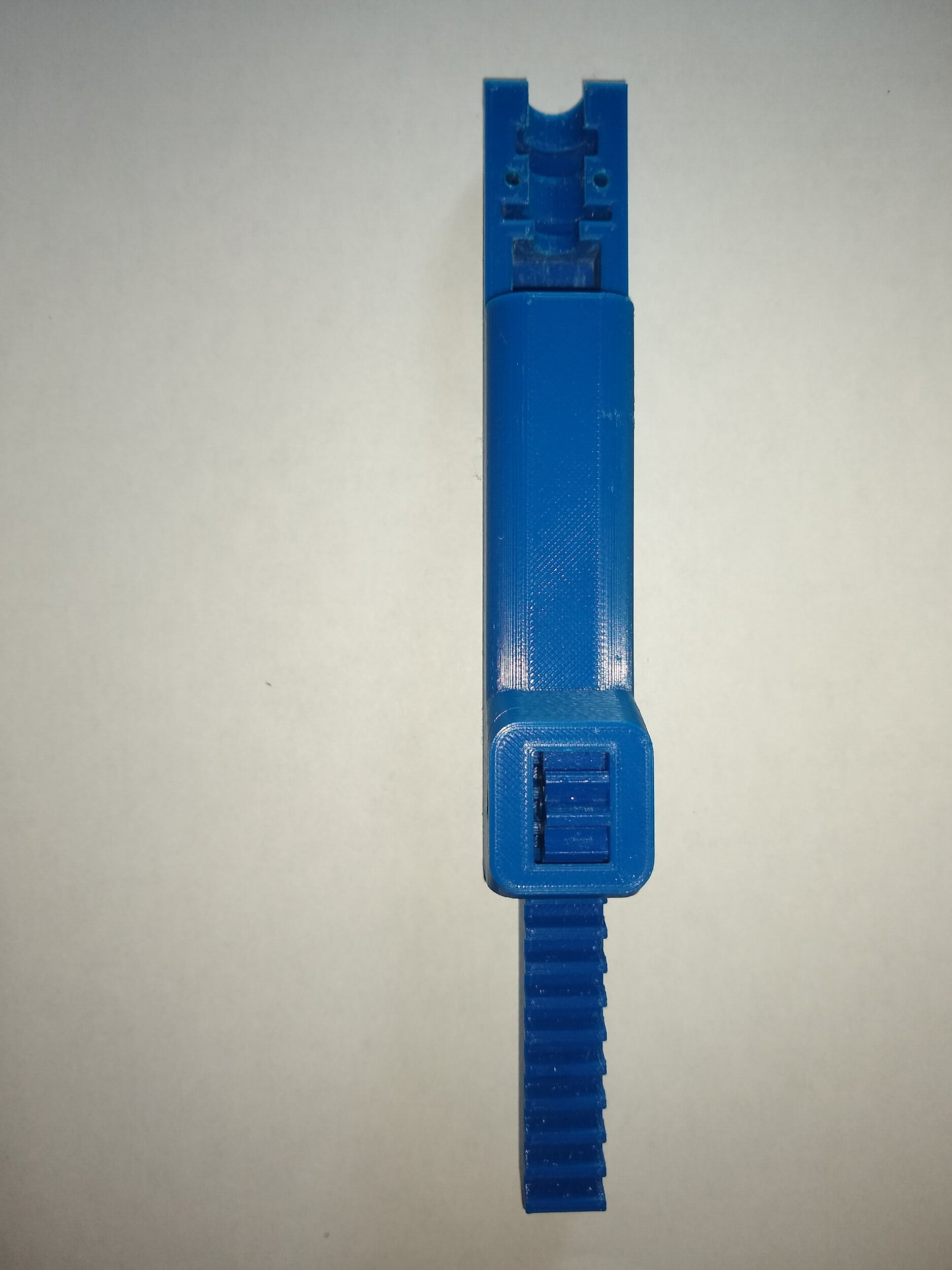
Place the Slide into the Body of the micropump. Carefully insert the Gear into its slot and ensure it fits. Place the Nozzle (with the sealed syringe in it) into the Body and ensure the Slide is in the proper location so that the end of the syringe plunger fits into the slot in the Slide. Play around with the partially assembled apparatus and ensure everything is functioning properly; if it is not, it may need some more sanding or slight modification. Everything should snap into place perfectly.
Screw the headless socket screw into the hole which holds the Gear into place. Ensure the Slide functions properly by rotating the Gear back and forth. Depending on the type of headless screw used, the Gear may wiggle slightly. This should not be a problem, as it should not engage the Slide and move it unless the Gear is intentionally rotated with applied pressure.
Place the Cap on the Body and ensure it tightly grips the Nozzle when held firmly into place with one’s hand. Insert the two 2.5 x 20mm screws (or whatever length chosen) into the holes on the Cap. Screw both of the screws in evenly and keep them relatively loose until they are both equally inserted. If they fit well and everything is working, tighten them until they are snug. The Nozzle should not be able to rotate or move when the Cap is properly tightened.
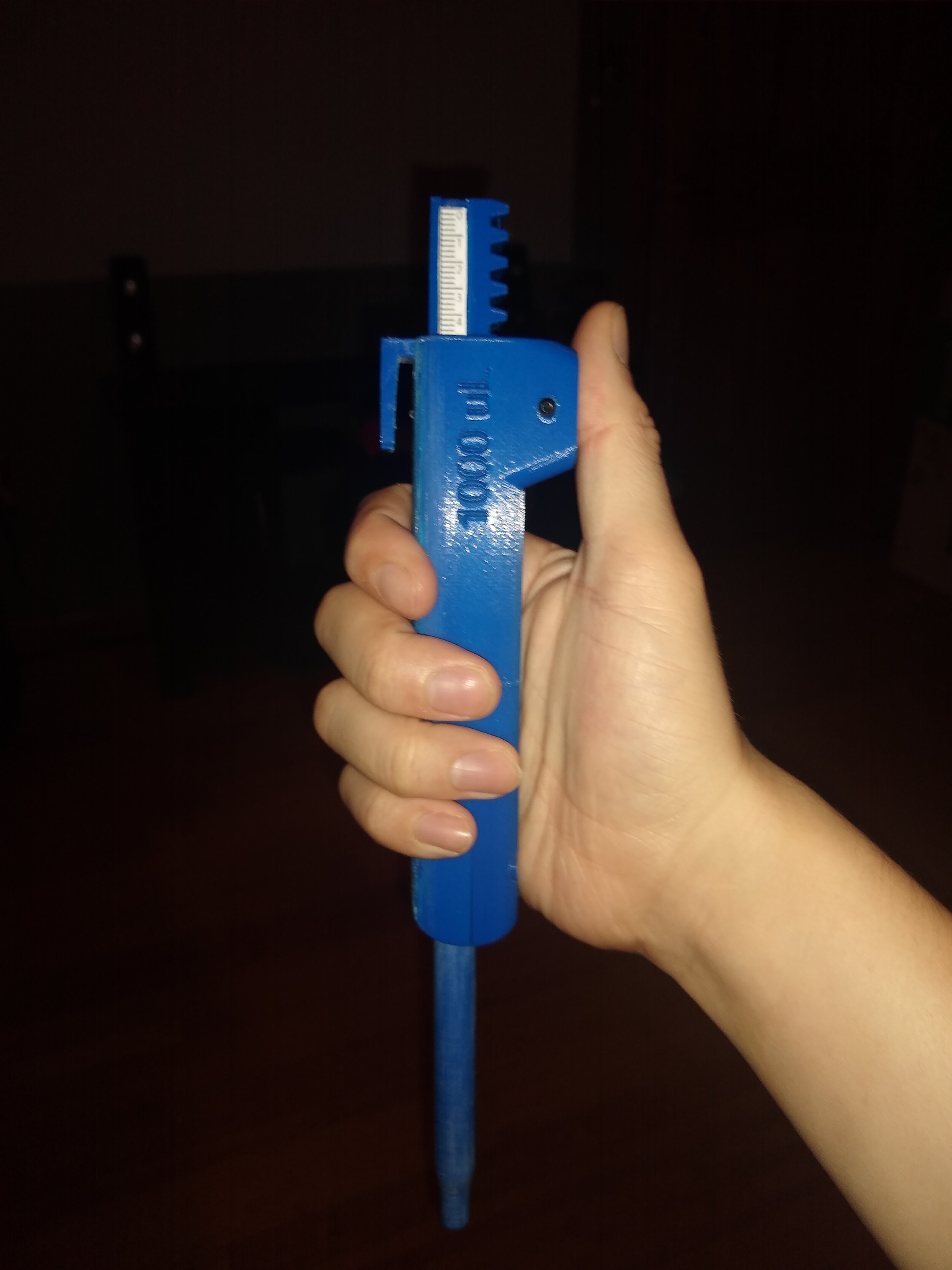
Print the Scale for the measurement of volume as noted in the article. You may glue the Scale onto the Slide as outlined in the publication in whichever way you see fit. In this case, the Scale was glued onto the Slide using 3M Scotch Clear Glue.
(Optional) During the process of removing the supports from the Body, the finger support/holder was accidentally broken off. The finger support/holder was glued back on using superglue. The Open source 3D-printed 1000 μL micropump is now completely assembled. Additional sanding of the tip of the Nozzle may be necessary to fit micro pipette tips.
Discussion and Questions:
The syringe was fairly loose when initially placed in the Nozzle, which makes one question if this exact syringe (1mL Norm-Ject luer lock syringe) is meant to be used. The point of this apparatus is to utilize commonly available parts. The publication mentions using a 1mL luer lock diabetic syringe, so this type of syringe may fit better. It doesn’t matter ultimately, as one can just add more epoxy when joining the syringe and Nozzle to ensure a snug fit and airtight seal. The syringe is used because it is hard to manufacture a perfect nozzle, which is responsible for maintaining the accuracy and precision of the volume of liquid drawn into the pipette. The beauty of using a standardized syringe in the nozzle is that it allows for minor defects in the 3D printed nozzle and the standardized syringe provides for the accuracy and precision of the apparatus.
This project was very simple and straightforward and required almost no deviation from the protocol established in the publication. Scale printing and gluing can be done in a number of ways and is left to the builder’s preferences.
See the publication (ref. 1) for data on accuracy and precision compared to other commercial micropipettes.
Results:
Conducted 11 trials at an ambient temperature of 24°C; In each trial, 1000 μL of de-ionized water was pipetted via the micropump equipped with a P1000 pipette tip. Each aliquot was dispensed into a pre-tared 10 mL beaker on an Ohaus Scout SPX1202. The weight of the aliquot of water was recorded for each of trial (11 trials total). The data was entered into Excel and the density of water at 24°C was used to calculate the volume of water dispensed for each trial. The measured weights of water and calculated volumes of water dispensed in each of the 11 trials were used to calculate the mean weight and mean volume of water dispensed. The sample standard deviation values for the weights and volumes of water dispensed were calculated. The average measured weight and average calculated volume of water dispensed by the micropump are represented in Figure 1 and Figure 2, respectively.
Obtained an average measured weight of water dispensed of 1.00 g ± 0.00447 (n = 11).
Obtained an average calculated volume of water dispensed of 0.997 mL ± 0.00425 (n = 11).
References:
Bravo-Martinez, J. Open source 3D-printed 1000 μL micropump. HardwareX 2018, 3, 110-116. https://doi.org/10.1016/j.ohx.2017.08.002


